A couple of weeks back I posted part 1– where I made a comparison of the different types of sensors I could use to count human activity in the stairwells of the MPEB where I am collecting a baseline of stair activity for my interactive floor project. I decided that PIR sensors offered the best compromise of reliability, cost and accuracy. I made a prototype unit which I set about testing in the building.
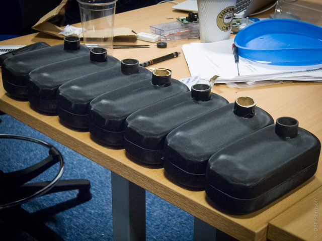
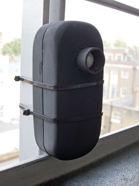
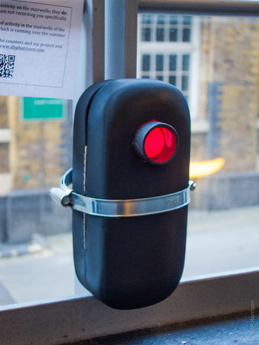
Everything seemed to go well- I’ve now made 8 of these counters, in nice containers, and have installed them in the building. I’ll check how many counts they’ve made early on Monday, which should give a good indication of their reliability (I’m not expecting too many counts as the weekend should be pretty quiet- if it’s a high number I’ll know something’s not working properly!). I’ll then start my baseline on Monday morning- just one week before the Olympics start, which is less than ideal!
Click “more” to see details of my build, the Arduino code, some photographs of them installed and future enhancements I’m hoping to make.
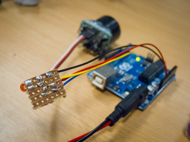
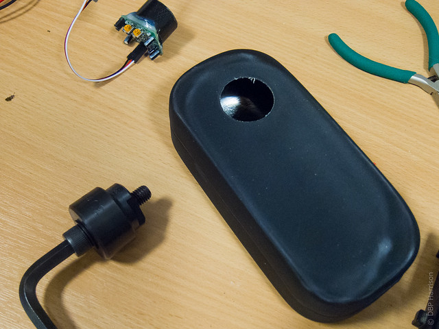
I made the necessary connections on a small piece of stripboard, including an LED so I can easily see when the PIR has detected activity. There’s four wires going to the Arduino (5v, ground, an input pin for the PIR, and an output pin for the LED), and three wires going to the PIR sensor (5v, ground and the sensor pin). I could’ve mounted this directly to the back of the PIR sensor, but I’ve got some spare room in the box and this gives a little more flexibility for the future.
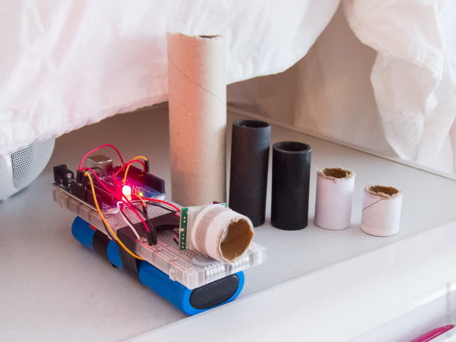
The PIR sensors I’m using have a field-of view of approximately 120°, this is rather too wide for my application (I only want to detect movement directly in front of the sensor), so I set about testing methods to cut this down a little. I tried taking the diffuser off of the unit, but this resulted in some rather unpredictable behaviour in terms of what was and wasn’t being detected. I eventually found that for my application, a tube with a length of 20mm, and an internal diameter of 24mm mounted on the standard diffuser was the best compromise between aesthetics, sensitivity and field of view. In my testing this has counted everybody moving within about 2-3m, and about 30° of the sensor.
Unsurprisingly, if you’re using a tube with a wider diameter it needs to longer in order to have the same effect, so do bare this in mind!
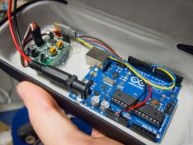
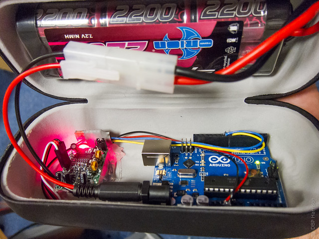
I’m using 7.2v radio-controlled car stick-packs made up of sub-C cells, which offer a fair amount of capacity(up to 3700mah) in a nice package- chargers aren’t too expensive either. They’re installed in funky metal cases, and jubilee-clipped onto the uprights of the stairs.
The code I’ve written is based on a slightly modified version of PIRsense, which was written for the Parallax PIR sensor (I’m using an unbranded version from eBay). I’ve added code so that the number of counts is written to the internal EEPROM of the Arduino, this has a finite lifetime of approximately 100,000 read/ write cycles. I’ve reduced the number of times I access the EEPROM as much as sensible- it is only written to every ten activations, which means that up to 9 counts could potentially be missed when I change the batteries or restart the unit to view the serial monitor.
The code I’ve written is below, hopefully the comments make everything clear, if not please get in touch.
[code lang=”c”]
/*
* PIRcount v1
* PIR Sensor activity counter, by Danny Harrison, dbpharrison.com.
* https://dbpharrison.com/general/pircount/
* Written 7th July 2012.
*
* Based upon the PIRSENSE code from Kristian Gohlke (see below), with the
* addition of an activation counter and EEPROM reading and writing. The counter
* saves to the Arduino’s EEPROM every 10 writes (to lower the number of read/ write
* cycles on the memory), allowing batteries to be changed, and the unit to be
* turned off.
*
* If power is lost before EEPROM is written between 0 and 9 activations may not
* be recorded. However, this will vastly lengthen the lifetime of the EEPROM.
* If you need more accurate readings, or a longer lifetime I’d recommend using an
* SD card and shield.
*
* The total number of activations is printed over serial after each activation,
* and when the unit is first connected.
*
* The counter can count up to 65,025 activations using two bytes in the EEPROM.
* 1,000 activations requires just 306 read/ writes to the EEPROM.
*
* When Pin 12 is connected LOW (Default is HIGH through "INPUT_PULLUP")
* the EEPROM counter resets to 0- use with caution!
*
*
******** Original Code *********
*
* Switches a LED according to the state of the sensors output pin.
* Determines the beginning and end of continuous motion sequences.
* author: Kristian Gohlke / krigoo (_) gmail (_) com / http://krx.at
* @date: 3. September 2006
*
* kr1 (cleft) 2006
*
* The sensor’s output pin goes to HIGH if motion is present.
* However, even if motion is present it goes to LOW from time to time,
* which might give the impression no motion is present.
* This program deals with this issue by ignoring LOW-phases shorter than a given time,
* assuming continuous motion is present during these phases.
*
********* End *************
*/
/////////////////////////////
//Variables
//the time we give the sensor to calibrate (10-60 secs according to the datasheet)
int calibrationTime = 10; //30 is default
//the time when the sensor outputs a low impulse
long unsigned int lowIn;
//the amount of milliseconds the sensor has to be low
//before we assume all motion has stopped
long unsigned int pause = 200;
boolean lockLow = true;
boolean takeLowTime;
int pirPin = 8; //the digital pin connected to the PIR sensor’s output
int ledPin = 7; //pin for the LED
int resetPin = 12; //pin to reset the EEPROM
int counterloop = 0; //for counting PIR activations before writing to EPROM. Writes every 10.
//Each byte of the EEPROM allows a value upto 255 to be stored, in order to allow
// more than 2,550 records we use 2 bytes, to up to 65.025 (255 x 255) values to
//be stored (allowing 650,250 people to be counted)
int EPmultiplier; //The first byte, for multiples of 255
int EPcounter; //Counter for 10’s- up to 255
//Number of people counted upto 255- used throughout code
int counter;
//overall number of people counted /10.
//Used to reduce the number of EEPROM reads and writes
int totalcount;
//include library for reading, writing and resetting EEPROM.
#include <EEPROM.h>
/////////////////////////////
//SETUP
void setup(){
Serial.begin(9600);
pinMode(pirPin, INPUT);
pinMode(ledPin, OUTPUT);
pinMode(resetPin, INPUT_PULLUP); //uses internal pullup resistor on pin
digitalWrite(pirPin, LOW);
delay(5000); //delay to allow terminal to be opened
/////////FOR TESTING boundary -SET TO 2550 people counted
//EEPROM.write(1,255);
//////Counter and Memory reading.
//Read the EEPROM and write it to serial to see how many people have been counted
//and fill the variables
EPmultiplier=EEPROM.read(0); //read the multiplier
EPmultiplier=EPmultiplier*255;// multiply by 255 to find the number counted
//Reads the actual amount counted in 10’s
EPcounter=EEPROM.read(1); //read the counter
//add the two parts together to calculate the entire number counted in 10’s
totalcount = EPmultiplier + EPcounter;
counter=EPcounter;
//print the counter number * 10 to get true value counted
//used for collecting data
Serial.print("EEPROM Counter: ");
Serial.println(totalcount*10);
delay(1000);
//////SET-UP of the PIR Sensor
//give the sensor some time to calibrate
Serial.print("calibrating sensor ");
for(int i = 0; i < calibrationTime; i++){
Serial.print(".");
delay(1000);
}
Serial.println(" done");
Serial.println("SENSOR ACTIVE");
delay(50);
}
////////////////////////////
//LOOP
void loop(){
//If the reset pin is LOW (connected to ground) then reset EEPROM and restart the sketch
//this allows the arduino to start counting from 0 without the need to connect to PC
if(digitalRead(resetPin) == LOW){
// write 0’s to EEPROM addresses 0 and
EEPROM.write(0, 0);
EEPROM.write(1,0);
Serial.println("EEPROM RESET!");
delay(50);
asm volatile (" jmp 0"); //this starts the sketch from the beginning.
}
////When the PIR sensor is activated.
if(digitalRead(pirPin) == HIGH){
digitalWrite(ledPin, HIGH); //the led visualizes the sensors output pin state
if(lockLow){
//makes sure we wait for a transition to LOW before any further output is made:
lockLow = false;
Serial.println("—");
Serial.print("motion detected at ");
Serial.print(millis()/1000);
Serial.println(" sec");
delay(50);
}
takeLowTime = true;
}
if(digitalRead(pirPin) == LOW){
digitalWrite(ledPin, LOW); //the led visualizes the sensors output pin state
if(takeLowTime){
lowIn = millis(); //save the time of the transition from high to LOW
takeLowTime = false; //make sure this is only done at the start of a LOW phase
}
//if the sensor is low for more than the given pause,
//we assume that no more motion is going to happen
if(!lockLow && millis() – lowIn > pause){
//makes sure this block of code is only executed again after
//a new motion sequence has been detected
lockLow = true;
Serial.print("motion ended at "); //output
Serial.print((millis() – pause)/1000);
Serial.println(" sec");
//counterloop is used to reduce the number of EEPROM writes needed.
//EEPROM is updated every 10 counts
counterloop = counterloop +1; //adds 1 to the counterloop
Serial.print("Counterloop: ");
Serial.println (counterloop);
Serial.print("total number counted: ");
Serial.println ((totalcount*10)+counterloop); //prints the entire number counted
//when the counterloop reaches 10 it writes one to the EEPROM and resets to 0.
if (counterloop == 10) {
Serial.println("Counterloop is 10… Updating EEPROM");
//////EEPROM handling
//Read EEPROM second byte (1)- EPcounter
counter=EEPROM.read(1);
//add one to the EEPROM
counter = counter+1;
///// The code below is for writing over two bytes
//If the counter has passed the limit of 1 byte (255), then add 1 to the multiplier
//and then set counter to 0
if (counter == 256) {
EPmultiplier=EEPROM.read(0);
EPmultiplier=EPmultiplier+1;
EEPROM.write(0,EPmultiplier);
//sets the EPcounter to 0
EEPROM.write(1,0);
}
//otherwise, there are less than 2,550 counted, so add 1 to the counter
else {
//Write the new value to the EEPROM
//counter var already stores the number counted.
EEPROM.write(1,counter);
}
//
Serial.println("EEPROM Updated.");
//reset the counterloop
counterloop = 0;
//adds 1 to totalcount
totalcount=totalcount+1;
}
delay(50);
}
}
}
[/code]
As you can see, I’m storing the number of counts into two bytes onto the Arduino EEPROM, this is a less than ideal solution, but does mean that I don’t need to use any additional hardware. A nicer method would have been to use something like the Adafruit data logging shield which includes a real time clock and SD card slot- this would allow me to timestamp and record each individual count. However, this will incur additional expense, and it won’t work with the additional shields I’ll be installing onto the Arduino in the future (I will be adding wifi modules soon).
One nice aside to the design is that when the PIR sensor is activiated an LED installed adjacently lights up (the LED is not necessary, but it’s useful feedback to see that they’re working!), this leaks through the PIR sensor and looks kinda funky!
I think the biggest limitation with this design, is that I need to plug each units into my laptop and use the serial monitor to read the number of counts. Wifi is currently being installed into the stairwells, once this is up and running I am intending to get the units writing to a MySQL database over wifi- this will mean that the only maintenance I will need to do to the units is changing their batteries every couple of days. The photograph added a photograph of an Arduino with a DFRobot Xbee shield and an RNXV wifi module
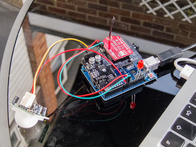
(Yes, I’m working outside in the sun!)
I’ll be using the same units with Cuecat barcode scanners to allow users to scan their ID cards as they’re climbing the stairs to collect game-time; more on these soon!
Amazing!
Thanks for share your project.
This is great, thanks for the share.
Impressive blog, good job there.
Do you sell any of your project?
I haven’t yet, but I’m not against it!
Ooh that great but can you tell me how to display the counter values using an Arduino LCD thanks man
To determine the meaning of the passage is necessary to have two sensors pir?
how to display the counter values using an Arduino LCDor digital counter??
Does anyone know?