Now that I’ve introduced the project as a whole this post will give a little more information on the interactive surface itself, and how it’s going to physically work.
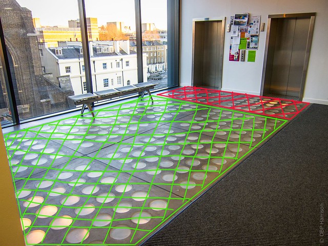
As previously mentioned, we’ll be using 218 of the 288 glass wells on the floor as a novel display- the area in red in the image below will not be used, to stop potential collisions between users of the lifts and those of the interactive surface.
A device including four RGB LED’s will be installed into each of the 218 wells, these will be installed on top of a plastic bung. The LED’s were cut in pairs from Adafruit LPD8806 strip, repositioned and then joined back together with fly-leads soldered. 6-pin JST connectors were then crimped onto the leads to allow each unit to connect to the adjacent one, as shown after the jump…
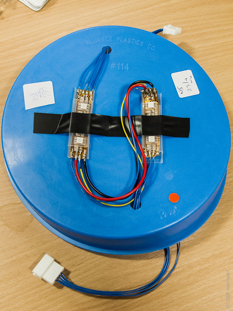
Each of these units will be connected in series, as a continuous strip. The LPD8806 strip allows us to independently shine each LED one of over 2 million different colours (or turn them off completely) through just four wires- power, clock and signal. This allows us to use the 864 LED’s in the project without the ridiculous mess of wiring that would be needed if they were connected individually. This does also means that the display will not work past a break in the wiring, but debugging should be fairly straightforward.
There is an Arduino library available for the strip, giving us a good basis for working with it, and a library from a previous project (more on this later) using the strip in a similar manner has also been written. Because of the current draw each set of 36 units (that’s 144 LED’s) will be powered independently, from a modified ATX power supply.
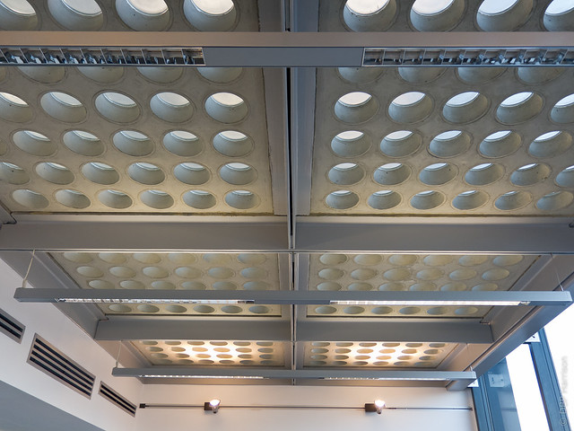
The photograph below shows the underside of the sixth floor, where the display will be installed, each of the blue-plastic bungs push-fit inside the holes in the concrete.
The entire display will be connected to an Arduino controlled by a Mac Mini, which will be located in an adjacent room along with the power-supplies.
A similar project was installed in the same surface, using the novel display to show energy usage and occupancy across the different floors of the building as part of a degree project. The image below shows the project during the installation and gives an idea of how the units will look once installed, although we will be looking into using a thin paper as a diffuser for the LED’s.
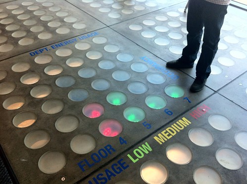
This project used the floor solely as a display, and used a smaller 4 x 4 grid. We’ll be using a much larger area of the floor (12 x 18) and will be allowing full-body interaction through the use of four Thermitrack cameras pointing down from the floor above to track movement across the surface.
Use of the interactive surface will be offered as a reward for climbing the stairs, I’ll explain how we’re tracking stair usage and how the different components work together in a future post.